Abstract
As wind energy developers start venturing into deeper waters with depths greater than 65 meters, the floating offshore wind turbines (FOWTs) are becoming the preferred solutions there over bottom-fixed structures. This paper summarizes the design of a semi-submersible platform for hosting a 15MW turbine. While semisubmersible origins from the oil & gas industry, the FOWT presents a different set of requisites and conditions for designing it. Recent existing and planned projects can be characterized by excessive use of steel and dimensions, compared to bottom-fixed structures. This paper aims to optimize the hull structure of a semi-submersible platform to be as cost-effective as possible while fulfilling the following design considerations: strength, vessel stability in still water and dynamic conditions, constructability, and operability. Meanwhile, the design is made to satisfy the rule requirements of major classification societies. Through a literature survey, data on existing semi-submersible projects is gathered and analyzed. The ratios of vessel displacement to hull steel weight relations are presented to show the trend. A high-level overview of class rules is given. An example platform, TaidaFloat, designed to carry a 15MW turbine is introduced. Its application is targeting a water depth from 65 to 100 meters with a deployment in Taiwan Strait in mind. The platform is designed against some limits and constraints, e.g. ensuring that it meets stability criteria. Its internal structural arrangement is preliminarily developed, and the steel weight is compared to recent projects. Features of the design are introduced, and their advantages are summarized. (工科海洋系馬開東教授提供)

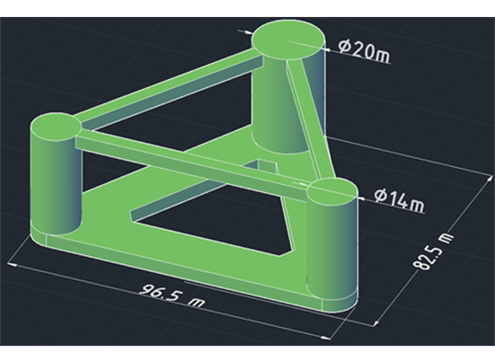
Figure 1 Hull shape of “TaidaFloat” finalized after an optimization process
1. INTRODUCTION OF SEMI-SUBMERSIBLE DESIGNS FOR FOWT
As wind energy developers start venturing into deeper waters with a depth greater than, say, 65 meters, the floating offshore wind turbines (FOWTs) are arguably becoming the preferred solutions over bottom-fixed structures [1][2]. This paper focuses on the design of semi-submersible platforms for FOWTs, among other choices such as spar, TLP, and barges. Currently, there are more than nine (9) projects with data available in the literature. They carry turbines ranging from 3.6 to 15 MW, from concept to demonstration projects; and some are already pre-commercial.

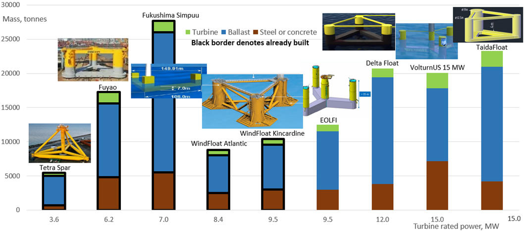
Figure 2 Principle characteristics and weight distribution in various semi-submersible hull designs
The first semi-sub floater, with commercial or pre-commercial scale, may be the WindFloat Atlantic and Kincardine; the latter supports a 9.5 MW turbine with relatively low hull weight and makes use of damping plates for increased stability. Most designs use a main column to carry turbines. It allows a quay-side crane to lift the turbine with relative ease. On contrary, there are designs that place the turbine in the center of the platform. For such a placement, installation of turbines may require a quay-side crane of extraordinary lifting capacity due to the reaching distance. VolturnUS has initially designed a 5 MW floater, however as the trend in FOWT is of a rapid increase in installed turbine power, it inclined them to upgrade to a 15 MW design. The already decommissioned Fukushima Simpuu has served as a good study case and turned attention to possible problems, it has also been the largest build in terms of platform size and displacement so far.
Taiwan has a recent development delivering a preliminary design, named DeltaFloat. It has the aim of supporting a large 12 MW turbine among competing designs. A 6.2 MW demonstration platform, Fuyao, was recently built in China, featuring a similar tri-column design. Also recently, the project claimed the smallest steel weight is Tetra Spar, which is not a pure semi-sub, but a more unconventional blend which works more like a spar. Its demonstration is underway and, if successful, it may provide an alternative with reduced use of steel metal.
The list of the projects [3][4][5][6][7][8] is shown in Figure 2, and there is a clear trend of decrease of required displacement over turbine weight for the newer projects, as designers strive to improve the efficiency. This paper aims to study those improvements and reconcile them, if possible.
2. DESIGN BASIS FOR A 15MW FOWT
This research is to determine the effects of different parameters on structure and performance of a FOWT semisubmersible. The platform is tentatively “TaidaFloat”, meaning NTU Float. The floater is made with the following design basis and considerations in mind:
- The floater must support a 15 MW turbine.
- Floater width shall not exceed 85 m to fit in the drydock of a Taiwanese shipyard.
- Floater’s metacentric height must be not less than 1.0 m as per major class societies’ rules.
- During operation, a floater’s pitch must stay below 10 degrees for the turbine to operate efficiently and safely.
- Draft shall not be less than 20 m to ensure that the pontoon is well submerged below the wave action zone in operation (ballasted) mode.
- Freeboard must be not less than 15m to reduce the chance of wave slamming and green water on the deck and horizontal bracing.

Figure 3 Changes in column sizing during the design process
However, as opposed to conventional designs with columns of the same diameter, TaidaFloat’s main column is made larger; this way, the buoyancy force acting on the main column is bigger, as illustrated in Figure 3. This design choice has a positive impact. Since the main column is heavier because of the turbine, its larger diameter provides the buoyancy to support the turbine weight. As a result, extra ballast is not required inside off columns to counterbalance the main column. Ballast can stay low in all three columns, instead of being high in the off columns. The advantage is that the center of gravity is lowered and thus initial and dynamic stability is improved. The ballast amount is chosen carefully so that the water levels in all columns are similar, allowing pumps to be placed at the same height in every column. With ballast spread more evenly among columns, the longitudinal bending moment in the hull may become smaller. Further, decreasing off column diameter has also led to a decrease in weight. Proper area and space are allocated for the top (deck) of the main column and the horizontal bracings; it may provide the personnel with a better working condition during operation and maintenance.
3. OPTIMIZING PRINCIPAL DIMENSIONS WHILE SATISFYING VESSEL STABILITY

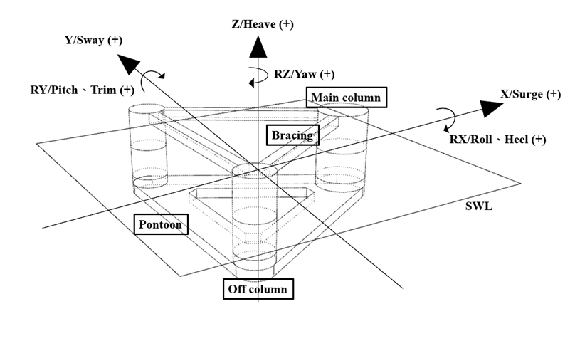
Figure 4 Floating platform reference coordinate system and components’ names.
Figure 4 shows the reference coordinate system and each component name used in this paper, all values reported in the work are with respect to this coordinate system.
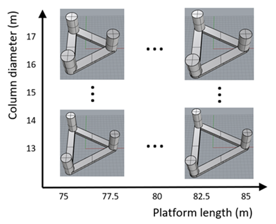
With triangular pontoon and three columns design, two main variables have the most profound effect on vessels displacement and stability; they are (1) platform length and (2) column diameter. Note that, for a triangular platform, the overall vessel length is shorter than the overall width as shown in Figure 1.

Figure 5 Twenty-five (25) platform shapes created by varying two variables, platform length and column diameter
4. CONCLUSIONS
This paper summarizes the process and results of the preliminary design of a semi-submersible hull, TaidaFloat, capable of carrying a 15MW wind turbine. The design of the floater is intended to serve as one of the best candidates suitable for deployments in the wind farms in Taiwan Strait of water depth ranging from 60 to 100 meters.
A design team was formed among researchers and engineers from National Taiwan University, SOIC, CSBC Corporation Taiwan. Two design variables, platform length and column diameter, are optimized to achieve a balance between platform size (or weight) and vessel stability.
The final design is a 3-columned semi-submersible with a ring pontoon capable of carrying a 15MW wind turbine of approximately 2300 tons. Several design features are achieved, including the following:
- The vessel has great stability that maintains a small trim/heel angle even when ballast-transfer pumps are not engaged. This is achieved through the proper positioning and sizing of the three columns, and the low center of gravity from the ring pontoon permanently ballasted with seawater.
- The hull shape adopts the conventional arrangement of columns with a ring pontoon, which has been a proven design in the oil and gas industry for decades. The ring pontoon, together with horizontal bracings, makes the entire vessel hull smooth and robust. The design minimizes the chance of fatigue cracking in complex bracings or isolated plane plates around columns.
- The main column is made larger so that the extra buoyancy may support the turbine weight. Less ballast is required inside off columns to counterbalance the main column. As a result, all three columns keep minimum ballast water only for trim/heel control. As there is no large amount of ballast stored in the off columns, the center of gravity is lowered, which improves initial and dynamic stability.
- The pontoon is designed as wide as practical to provide damping. In other words, the wide pontoon reduces vessel motions, e.g. heave. The pontoon is filled to the brim with ballast water to balance the pressure inside and outside and increase stability. The mass of the ballast water also helps in reducing vessel motions.
- Generous area and space are provided for the top (deck) of the main column, and the three horizontal bracings. It gives a better working condition during operation and maintenance.
With the preliminary design presented in this paper, the project will tackle several challenges in the next phase. One of these is mooring design, as it is questionable whether a 3x1 system could withstand the maximum design condition in a 50-year typhoon. A preliminary analysis performed in this project has shown that a 3x2 system may be needed.
Another one of the challenges, arguably, is the weight control of steel. It may not be an easy task to reduce the steel weight by a large amount, as the design practice is to follow the design formula set in class rules. It remains to be seen how an efficient hull design can be achieved through finite element analysis. It may be a challenge to reduce the material and construction cost of a FOWT to the point that it can be economically competitive compared to those fixed offshore turbines in shallower waters.